So, somebody asked me the other day how all this started. My hobby was to fix smartphones, just for fun. I will get broken phones from my friends and I will open them up, see if I can learn something from them and try to figure out how to fix them, but after the 20th phone, I grew tired of it.
I was looking for a new hobby something fresh, something different, one day I just got a digital copy of Wired Magazine from a friend and I found a really interesting article titled "Here Comes the Drones", I think I read it like 5 times, kept thinking about it, and I start talking about it a lot, showing the article to a lot of people, I thought I found exactly what I wanted to do.
While I was talking about the idea to build one, a colleague from work , Roberto, asked me if he can be part of it, I thought it was a good idea, actually it was the best idea, honestly if it wasn't for him maybe I would it left the project in just that a project that I didn't finish, but Roberto's energy and enthusiasm kept us going, we talked about creating a log, a journal of everything that we do, and he came up with this blog.
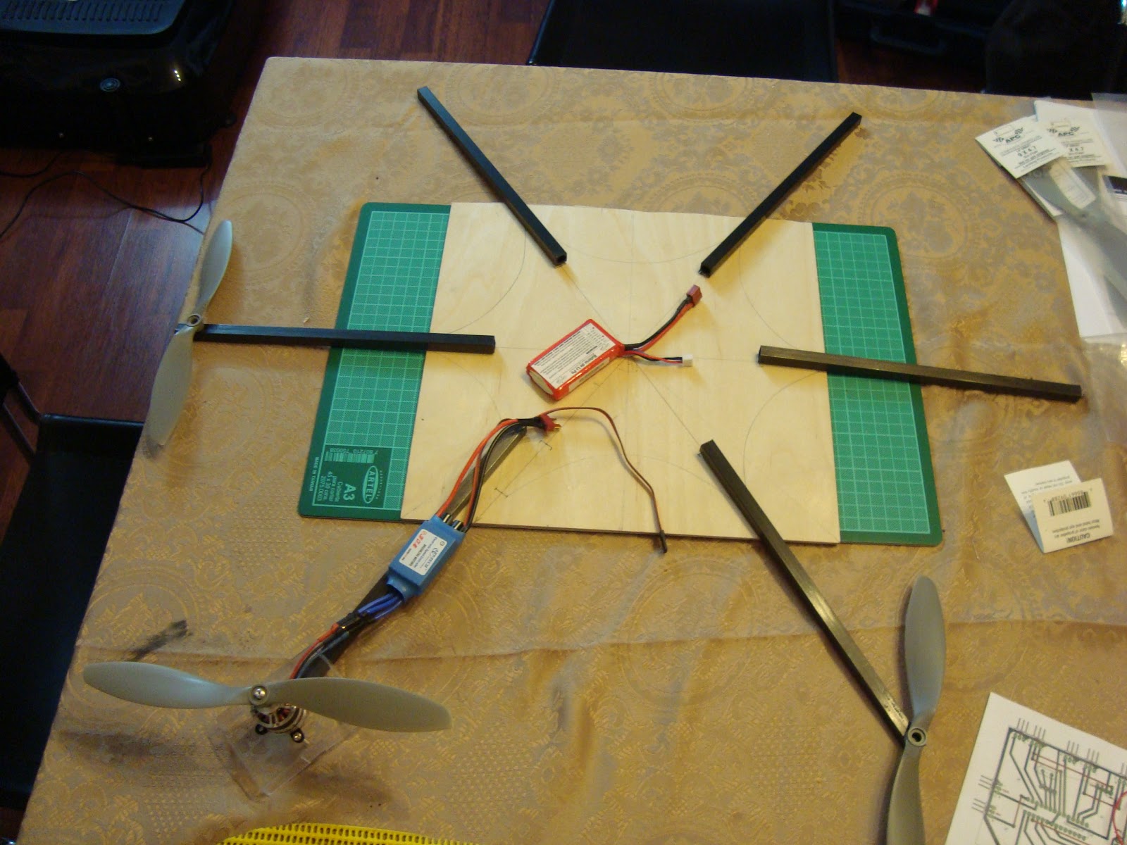
I thought to make it all of plywood as some models I saw on the net. I got a clear idea of how I wanted to look like, but Roberto had a better idea as he researched the fiber carbon tubes, it made it lighter, we still used the center wheel made in wood.
Roberto has been doing all the electronics, I am really rusty in this part, the more we work on it, the more things we want to add and see if they work or not, I got some IR proximity sensors and we will see if we can add it to the project.
We hope this blog helps people who are interested in building an Hexacopter from scratch, the most important part is....Enjoy!
Friday, December 28, 2012
Wednesday, December 12, 2012
Research
We will post here all resources from the net that we got ideas from or that we learn from.
Balance Filters:
http://web.mit.edu/scolton/www/filter.pdf
Kalman Filter:
http://arduino.cc/forum/index.php/topic,58048.0.html
http://www.instructables.com/id/Guide-to-gyro-and-accelerometer-with-Arduino-inclu/
http://en.wikipedia.org/wiki/Kalman_filter
ESC Calibration:
http://code.google.com/p/
Stabilization System:
http://technicaladventure.
http://diydrones.com/forum/topics/quadcopter-control-function-layers
Some values for reference:
ITG-3200 Triple Axis Gyro:
ADXL345 Accelerometer:
http://www.sparkfun.com/tutorials/240
6 Degrees of Freedom - Sparkfun:
http://bildr.org/2012/03/stable-orientation-digital-imu-6dof-arduino/
6 Degrees of Freedom - Sparkfun:
http://bildr.org/2012/03/stable-orientation-digital-imu-6dof-arduino/
Arduino - Adding more interrupts To Read More RC Channels:
DJI Flame Wheel:
Understanding how Accelerometers and Gyros work:
Eagle: Schematics
and libraries:
Burning the bootloader to the ATMEGA chip:
Controlling the ESCs using the Arduino Servo.h library:
Understanding PPM (in order to read the R/C channels and write to the ESCs):
Tuesday, December 11, 2012
HW and SW Tests
We are using a DJI F550 frame to test the electronics and our first version of software (actually, 2 frames are being used... :)
Once we have both working well, then it will be installed on the frame we are building.


Comparing the frames:

First test. Testing the PCB with the ATMEGA328 chip:
The electronics works! And apparently the first idea on how the microcontroller controls the hexa works too.
This test was made without calibrating any of the ESCs. We can notice that there is a small difference in the response between them. Next step will be calibrating the ESCs.
Once we have both working well, then it will be installed on the frame we are building.
Comparing the frames:
First test. Testing the PCB with the ATMEGA328 chip:
The electronics works! And apparently the first idea on how the microcontroller controls the hexa works too.
This test was made without calibrating any of the ESCs. We can notice that there is a small difference in the response between them. Next step will be calibrating the ESCs.
Shopping List
(2) Carbon Fiber tubes 1cm by 1cm [cost USD / CLP]
(2) Plywood [cost USD / CLP]
(1) Balsa Block 3x3x12 [cost USD / CLP]
(12) screws [cost USD / CLP]
(12) nuts [cost USD / CLP]
(2) 12 gauge cable [cost USD / CLP]
(1) battery 3200mAh 11.1v 3 LI-PO [cost USD / 39000 CLP]
(6) ESC TURNIGY Plush 30amp Speed Controller [11.91 USD / CLP]
(6) Turnigy Park480 Brushless Outrunner 850kv [19.37 USD / CLP]
(3) CW Blades / Regular Blades [cost USD / 1200 CLP]
(3) CCW Blades / Reverse Blades [cost USD / 2000 CLP]
Customs Import Taxes
Monday, December 10, 2012


Monday, November 19, 2012
The Electronics
The Electronics of the first version will be just the ATMEGA328 chip from the Arduino Uno, the crystal (clock), the input connectors (Rx Channels), the output connectors (ESCs) and the connectors for the 2 remaining digital ports and the analog ports, letting the board ready for some expansion.
Screenshots from Eagle:
LED – D13
Screenshots from Eagle:
 |
| Schematic |
 |
| PCB |
Input/Output and
Arduino Digital Pins Mapping:
Outputs (PWM pins):
ESC1 – D3
ESC2 – D5
ESC3 – D6
ESC4 – D9
ESC5 – D10
ESC6 – D11
LED – D13
Inputs:
Rx1 – D2 (Aileron)
Rx2 – D4 (Elevator)
Rx3 – D7 (Throttle)
Rx4 – D8 (Rudder)
Rx5 – D12 (Extra) - Parachute
deployment?
ESC1 will provide power (5v) to R/C
receiver
ESC2 will provide power (5v) to the
ATMEGA328 chip
The positive teminal of ESC3, ESC4,
ESC5 and ESC6 will be disconnected.
I used optiLoader by Bill Westfield to burn the bootloader to a blank ATMEGA328 chip.
The procedure can be found here:
http://www.3guys1laser.com/blog-burn-bootloader-blank-atmega328atmega328p-arduino-uno
I used optiLoader by Bill Westfield to burn the bootloader to a blank ATMEGA328 chip.
The procedure can be found here:
http://www.3guys1laser.com/blog-burn-bootloader-blank-atmega328atmega328p-arduino-uno
Thursday, November 15, 2012
First R/C Test Using Arduino Uno
The objective of this test was to learn how to read the R/C (Radio Control) receiver signal, convert it and write the correct values to the speed controller. For this test, just one motor is being used.
First step:
Reading the R/C Receiver signal from channel 3, print them on the screen in order to know the min and max values, and then convert the input range to the output range (ESCs' range)
ESC - Electronic Speed Controller
So, the channel 3 of the R/C receiver was connected to the Arduino's digital pin 2 and this was the code used to establish the connection:
attachInterrupt(2,rc1,CHANGE);
By this time I just knew this way to make the connection between the Arduino and the R/C receiver:
Later I found out that the Arduino UNO has just 2 external interrupts (pins 2 and 3), which would limit us to read just 2 PPM channels (for the hexa control, we need at least 4).
This was solved by using the PinChangeInt.h library and this code to establish the connection:
Min = 1108
Max = 1900
So the range is almost the values accepted by the ESCs (in microsseconds - distance between the PPM pulses). But, the min value happens when the throttle control is on the top, and the Max value is when the throttle control is at bottom position. This way, we needed to convert the range using the map function so we could write the correct values to the ESC:
Using angles:
map(RCVal1, 1900, 1108, 0, 180)
Using microseconds:
map(RCVal1, 1900, 1108, 1000, 2000)
Second step:
Connect the ESC to the digital pin 11 and write the correct values to it according to the input from the R/C control.
There are 2 ways of writing the values to the ESC. First I used the servo angles, using:
0 - as the minimum speed, and
180 - as the maximum speed
servo1.write(map(RCVal1, 1900, 1108, 0, 180));
It works, but after testing by writing the microseconds, I had the impression that this way is more accurate (better response). So, this is the code that is being used:
servo1.attach(11);
servo1.writeMicroseconds(map(RCVal1, 1900, 1108, 1000, 2000));
The Hardware config was:
R/C >>> R/C Receiver ---> Arduino Digital Pin 2 as input --> Software --> Arduino Digital Pin 11 as output (PWM) --> ESC --> Motor
Here is the result:
First step:
Reading the R/C Receiver signal from channel 3, print them on the screen in order to know the min and max values, and then convert the input range to the output range (ESCs' range)
ESC - Electronic Speed Controller
So, the channel 3 of the R/C receiver was connected to the Arduino's digital pin 2 and this was the code used to establish the connection:
attachInterrupt(2,rc1,CHANGE);
By this time I just knew this way to make the connection between the Arduino and the R/C receiver:
Later I found out that the Arduino UNO has just 2 external interrupts (pins 2 and 3), which would limit us to read just 2 PPM channels (for the hexa control, we need at least 4).
This was solved by using the PinChangeInt.h library and this code to establish the connection:
PCintPort::attachInterrupt(THROTTLE_IN_PIN, rc1,CHANGE);
By using this code we are able to use any digital port of arduino to read the R/C signals.
This was used to determine the min and max values of the throttle:
Serial.println(RCVal1);
Min = 1108
Max = 1900
So the range is almost the values accepted by the ESCs (in microsseconds - distance between the PPM pulses). But, the min value happens when the throttle control is on the top, and the Max value is when the throttle control is at bottom position. This way, we needed to convert the range using the map function so we could write the correct values to the ESC:
Using angles:
map(RCVal1, 1900, 1108, 0, 180)
Using microseconds:
map(RCVal1, 1900, 1108, 1000, 2000)
Second step:
Connect the ESC to the digital pin 11 and write the correct values to it according to the input from the R/C control.
There are 2 ways of writing the values to the ESC. First I used the servo angles, using:
0 - as the minimum speed, and
180 - as the maximum speed
servo1.write(map(RCVal1, 1900, 1108, 0, 180));
It works, but after testing by writing the microseconds, I had the impression that this way is more accurate (better response). So, this is the code that is being used:
servo1.attach(11);
servo1.writeMicroseconds(map(RCVal1, 1900, 1108, 1000, 2000));
The Hardware config was:
R/C >>> R/C Receiver ---> Arduino Digital Pin 2 as input --> Software --> Arduino Digital Pin 11 as output (PWM) --> ESC --> Motor
Here is the result:
Getting Started
Ok... The first version of our hexacopter will not have accelerometer and gyro for flight stabilization. Those components will be added once the first version is up and running... or up and flying? :)
First thing was to figure what parts we needed to buy to start to build the structure.... and the electronics. Also, the most expensive part of the project: the R/C.
First list of parts and components:
- Futaba 6 Channels 2.4GHz R/C (one for each engineer)
- Carbon fiber square tubes
- Wood
- Screws and nuts
- The amazing Dremel tool
- 9 x 4.7 Propellers (CW and CCW)
- Turnigy Park480 Brushless Outrunner 850kv
- Turnigy Plush 30amp Speed Controllers AT


For the electronics, we are currently using the arduino uno for the tests, but the arduino board will not be used. The ATMEGA328 chip will be removed from the board and put in the pcb that we are going to build. For that, we will need some additional electronic components, such as:
- PCB
- PCB Ferric Chloride
- ATMEGA328 chip
- ATMEGA328 chip socket (28 pins)
- 16 MHz Crystal (clock for the ATMEGA chip)
- 22pF ceramic capacitors
- Pin headers for connecting the Rx Channels and ESCs (regular and 90°)
- 12 gauge cables for the power (the first version will have a power distribution made of cables)
First thing was to figure what parts we needed to buy to start to build the structure.... and the electronics. Also, the most expensive part of the project: the R/C.
First list of parts and components:
- Futaba 6 Channels 2.4GHz R/C (one for each engineer)
- Carbon fiber square tubes
- Wood
- Screws and nuts
- The amazing Dremel tool
- 9 x 4.7 Propellers (CW and CCW)
- Turnigy Park480 Brushless Outrunner 850kv
- Turnigy Plush 30amp Speed Controllers AT
For the electronics, we are currently using the arduino uno for the tests, but the arduino board will not be used. The ATMEGA328 chip will be removed from the board and put in the pcb that we are going to build. For that, we will need some additional electronic components, such as:
- PCB
- PCB Ferric Chloride
- ATMEGA328 chip
- ATMEGA328 chip socket (28 pins)
- 16 MHz Crystal (clock for the ATMEGA chip)
- 22pF ceramic capacitors
- Pin headers for connecting the Rx Channels and ESCs (regular and 90°)
- 12 gauge cables for the power (the first version will have a power distribution made of cables)
Subscribe to:
Comments (Atom)